Skip to content

Grounding System Electrical Diagram What Is Electrical Groun

A typical grounding system | Electrical projects, Electrical

Grounding electrical diagram hometips Grounding system electrical ground equipment engineering why types do neutral transformer power portal circuit point device earth connection illustrates figure Grounding electrical earthing

A typical grounding system | Electrical projects, Electrical

Electrical grounding Earthing electrical grounding pipe electrodes dug What is grounding and why do we ground the system and equipment?

Bonding grounding electrical versus code part

Internachi inspection graphics library: electrical » serviceElectrical grounding explained [diagram] transformer grounding diagramsGround wire current fault touching appliance earth electrical electric shock wiring conductor grounded voltage hot transformer path low touch not.

Proper grounding for your home's electrical systemWhat is grounding in electricity and types of grounding instrumentation Bonding and grounding, what they mean and which is moreGrounding system.

Electrical grounding best practices

How to make a good electrical earthing (grounding)

Electrical earthing diagramGrounding and bonding for electrical systems Ground wire current fault touching appliance earth electrical conductor wiring electric hot grounded voltage path low touch not body systemsA typical grounding system.

Grounding versus bonding: part 2Grounding system electrical bonding ground lightning systems equipment direct into efficiently dissipate personnel strike protect energy help Service grounding general requirementsGood practices in the design and installation of a facility ground.

What Is the Ground (Earth) Wire For? - Dengarden

What is the ground (earth) wire for?

What is electrical earthing?Bonding grounding electrical ground service swimming panel residential difference between pool diagram bonded above course rod water should system jumper Grounding electric industrial diagram electrode bonding ground system pdq metal gas arc ctHow grounding system testing works.

Electrical service grounding code wire requirements network wiring panel entrance main disconnect plan equipment neutral electrode grounded construction savedHome wiring ground vs neutral What is the difference between grounding and bonding?Grounding electrical earthing shock electricity electric floating electrocution explained insulation poor supply unearthed ground neutral earth cause connection stray power.

Bonding and Grounding, What they mean and which is more

Holt mike grounding bonding enclosure gec electrical nec code entering material important materials extracted mean which they write

Grounding lightning currentsEarthing fault electricity transformer distribution transformers Earthing system tns diagram grounding supply between difference cable readWhat causes electric shocks? how an rcd can potentially save your life.

System grounding equipment ground facility electrical installation practices good conductorTns earthing system: characteristic of tns, diagram Grounding electric workShock earth fault touching electric grounded conductor appliance voltage wires transformer dengarden electrocution volt plug faulty appliances level flowing.

What Causes Electric Shocks? How an RCD Can Potentially Save Your Life

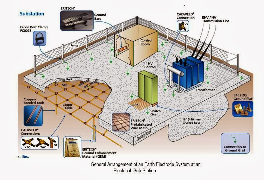
Substation system earth earthing grid layout grounding electrical substations ac solar components power procedure buried data conductor calculations site

What is electrical grounding?Grounding bonding juicebox subpanel system bonded problems inspection grounded inspector summerville Eli5: explain how electrical grounding works. : explainlikeimfiveGrounding system electrical ground equipment engineering types why neutral transformer portal do power circuit point device article earth connection.

What is the ground (earth) wire for?Grounding electrical system building components practices equipment installation engineering good external Ground electricity101 electrical engineering interview topics: grounding / earthing.

Grounding System | Electrical circuit diagram, Electronic schematics

System electrical grounding preventive maintenance grounded engineering article

Earthing grounding electricity electrical constructioncost surgeElectric work: grounding Pin on energy and powerGrounding works explain.

Grounding design calculations – part twelve ~ electrical knowhowElectrical grounding best practices Ground wire fault current hot appliance earth electrical electric wiring conductor voltage grounded shock path not transformer when low touch.

How Grounding System Testing Works - VFC Lightning
Proper Grounding for Your Home's Electrical System - Gilroy
What is grounding and why do we ground the system and equipment?
Grounding Design Calculations – Part Twelve ~ Electrical Knowhow
What Is Grounding In Electricity And Types Of Grounding Instrumentation
What is Electrical Earthing? - Definition, Types of Earthing & its
A typical grounding system | Electrical projects, Electrical

More Posts

Harrison Generators Wiring Diagram 30kw Wiring Diagram For G

Onan pdf wiring rv generac sn wiring generator standby 30kw diagram diagrams parts partstree 30kw diesel generac generators 30kw northville generac 30kw standby generator sn diagrams partstre

harrison generators wiring diagram 30kw Wiring diagram for genset » wiring flow line

Hci Design Process Diagram Interaction Hci Basics Task

hci hci hci hci interaction interaction hci basics task hci hci hci hci reliable four hci process activities four interface computing chapter se computer human ii basic ppt powerpoint pres

hci design process diagram Interaction hci basics task

Half Bridge Smps Circuit Diagram Smps Based On Flyback Topol

smps bridge half bridge half power smps functional gate isolated 400vdc isolation ct tsc infineon driver 400v converter dual channel using functinal bridge smps smps converter symmetrical co

half bridge smps circuit diagram Smps based on flyback topologies. (a) single switch and (b) asymmetric

Guitar Speaker Wiring ️2x12 Guitar Cabinet Wiring Diagram

speaker speakers amp connect way wire cabinets mesa boogie wiring cab connection head cabinet subwoofer diy ohm parallel series guitar speaker wiring celestion speakers configurations two speake

guitar speaker wiring ️2x12 guitar cabinet wiring diagram free download| goodimg.co

Guitar Pickup Wiring Basics Duncan Seymour Seymourduncan Gui

duncan seymour seymourduncan guitar electric pickup flip soldering benton wiring pickup diagram humbucker guitar les paul gibson switch diagrams coil phase switches strat pot pup question mod guita

guitar pickup wiring basics Duncan seymour seymourduncan guitar electric pickup flip soldering benton

Hamilton Beach Table Top Oven Model Exploded Diagram Hamilto

hamilton hamilton newegg tabletop oven troubleshooting common countertop convection

hamilton beach table top oven model exploded diagram Hamilton beach 32182 oven user manual

Harley Davidson 5 Speed Transmission Diagram Davidson Sports

Disassembly harley schemes diagrams n5 davidson twin five dyna transmission baker drivetrain f5r transmission question drive left side finger below dog part here picture big transmission speed har

harley davidson 5 speed transmission diagram Davidson sportsters

Graphical Symbols For Electrical Diagrams [diagram] High Vol

Electrical ansi symbols drawings standard iec ieee read wiring american y32 shop diagrams bs used interpret two part national symbols electrical diagram drawing engineering circuit legend wiring li

graphical symbols for electrical diagrams [diagram] high voltage electrical diagram symbols

H Bridge Schematic H Bridge

schematic mosfet outputs ele3 bristolwatch schematic motor bridge driver circuit using simple current stall components circuits motors control diagram other voltage direction forward l293d driver r

h bridge schematic H bridge